


New


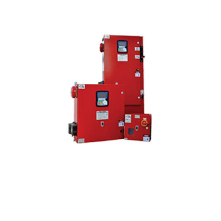
Centrifugal Vertical Turbine Fire Pumps
- All Pumps are Hydrostatically Tested to minimum of 150% of its Maximum Working Pressure and can withstand Double the Max.Working Pressure.
- All Pumps have Clock-Wise Rotation when viewed from the Driver Side.
- All Pumps are Multistage with 2 stages as minimum requirement.
- “The rated speed marked on the pump can vary within +/-4% of the listed/ approved rated speed example: 3000 RPM pump can be driven with 2900 RPM Drivers.”
| Model No. | Capacity (GPM) | UL,SETSCO & CE Listed Net Pressure (PSI) | Number of Stages | FM Approved Rated Net Pressure (PSI) | Number of Stages | Approx Speed (RPM) |
|---|---|---|---|---|---|---|
| SFP-200-70VT | 200 | 40 – 248 | 2 – 12 | 40 – 289 | 2 – 12 | 1480 |
| SFP-200-70VT | 200 | 48 – 348 | 2 – 10 | 64 – 348 | 2 – 10 | 1480 |
| SFP-200-30VT | 200 | 60 – 305 | 2 – 6 | 2900 | ||
| SFP-200-30VT | 200 | 63 – 323 | 2 – 6 | 2980 | ||
| SFP-200-30VT | 200 | 64 – 327 | 2 – 6 | 3000 |
Description
Attachment
Related products


Fire doors and frames
Fire doors and frames
As part of our continuous pursuit of innovation, SFFECO has launched its world-class fire rated doors and frames. The fire doors and frames are manufactured in a fully automated factory using CNC machines thus ensuring uniform quality and a great finish. SFFECO fire doors are manufactured to comply with various architectural requirements. These doors are designed for areas where strength, stability and durability are priorities. Typical applications include industrial building entrances, shop service doors, basement floors, stairwells, and elevator shafts. It is also widely used as partition or exterior doors in electrical and petrochemical plants. The door or frame can be made of cold rolled steel, galvanized steel or stainless steel. Doors can be used in drywall and masonry construction.

Photoelectric smoke detector
Model No.: LE-SOC-24V
Features
Computer Designed Non-directional Smoke Chamber
360° View of Detector Case
Low Profile, 1.8" Height (with Base)
2 or 4 Wire Base Compatibility, Relay Bases Available
Very Stable Operation, RF/
Standby Current Transient Protection Low, 59μA at 24VDC
Two Built-in Power/Sensitivity Lights for Supervision/Alarm
The automatic sensitivity window check function meets the requirements specified in NFPA 72, Chapters 2 and 7, Inspection, Testing, and Maintenance.
Centrifugal Horizontal Split Case Fire Pumps
- All Pumps are Hydrostatically Tested to minimum of 150% of its Maximum Working Pressure and can withstand Double the Max.Working Pressure.
- All Pumps have Clock-Wise Rotation when viewed from the Driver Side.
- All Pumps are horizontal single stage Pumps.
- “The rated speed marked on the pump can vary within +/-4% of the listed/ approved rated speed example: 3000 RPM pump can be driven with 2900 RPM Drivers.”
| Model No. | Rated Capacity (GPM) | Size (SucXDis) | UL Listed Rated Net Pressure Range (PSI) | FM Approved Rated Net Pressure Range (PSI) | SETSCO & CE Rated Net Pressure Range (PSI) | Approx Speed (RPM) | Max Working Pressure (PSI) |
|---|---|---|---|---|---|---|---|
| SFP150-25SH | 150 | 6 x 4 | 114-208 | 114-208 | 114-208 | 3500 | 300 |
| SFP150-25SH | 150 | 6 x 4 | 121-220 | 121-220 | 121-220 | 3600 | 300 |
| SFP150-40SM | 150 | 6 x 4 | 206-289 | 206-289 | 206-289 | 2900 | 385 |
| SFP150-40SM | 150 | 6 x 4 | 221-310 | 221-310 | 221-310 | 3000 | 385 |
| SFP150-SN31SH | 150 | 6 x 4 | 226-316 | 226-316 | 226-316 |