


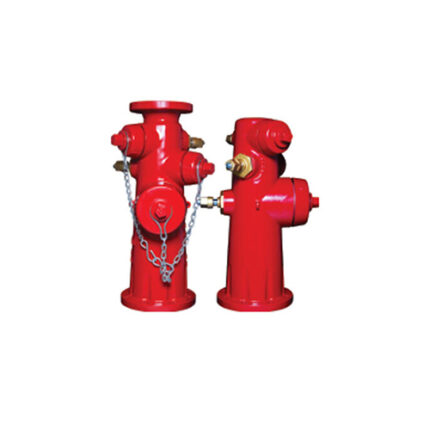
Wet barrel fire hydrant
DESCRIPTION MATERIALS SPECIFICATIONS Model
LF-WBHX-115 / LF-WBHX-100
Faucet, Wet Barrel Type, 6" Diameter Made of Ductile Iron, with
Single 4.5" Pump Connection (4" Pump Connection Optional
). 2.5" Thread Hose Outlet Connections and Connectors
, AWWA C503, Flangeless 4" Display, UL\FM
Approved, LIFECO
Model LF-WBHM-115 / LF-WBHM-100
Faucet, Wet Barrel Type, 6" Diameter Made of Ductile Iron, With
Single Pump Connection 4.5” (4″ Pump Connection
Optional) Thread and Hose Outlet Connections 2.5”
Thread, AWWA C503, With Only 4” Flange Display, UL\FM
Approved, LIFECO
Features
Strong Ductile Iron Material for Long Service Life
Pressure Rating Higher at 250psi and 2 times
the 500psi test pressure
• Choice of multiple hose nozzles
• Internal and external fusion bonded epoxy coating
• FM approved and UL Listed for use in
fire protection application
• Observation flange available for additional hardware
Technical Specifications
• Design Standard: FM1511 / UL246 / AWWA C503
• Nozzle Thread Standard: NFPA1963
• Pressure Working: 250 psi
• Inlet Flange Connection in ANSI Class 125/150 6"
BS EN 1092-2PN110 / 16 6”
• Observation Flange Connection in ANSI Class125/150 4”
• Hose Nozzle: 2.5″ * 2
• Nozzle Pump: 4.5” * 1 (4” pump connection optional)
• Monitor Flange Connection 2H1PM: ANSI Class125 / 1504 “
BS EN 1092-2 PN10 / 16 4”
• Inlet Flange Connection: ANSI CIass125 / 150 6”
BS EN1092-2 PN10/16 6”
Component Material No.
1 Hydrant Body 65-45-12
2 Steel Wire Rope
3 0 EPDM Ring
4 Fire Engine Nozzle Cap 65-45-12
SS304 Plastic Coated
5 Fire Engine Nozzle C84400
6 Fire Engine Nozzle EPDM Gasket
7 4.5” Gland C F8
8 Inner Flat Angle Set Six Corners Spoiled A 2 9 4.5” EPDM Sealing Ring Disc
10 Disc 4.5” CF8 11 55304/55420 12 Fixed Nut CF8 13 Inner Six Cylinder Angles Head Cover A2.70 14 C84400 15 C & 8 16 Hex Nuts 4.5” Shaft Nut A2.70 17 Hose Nozzle Cap Run Nut

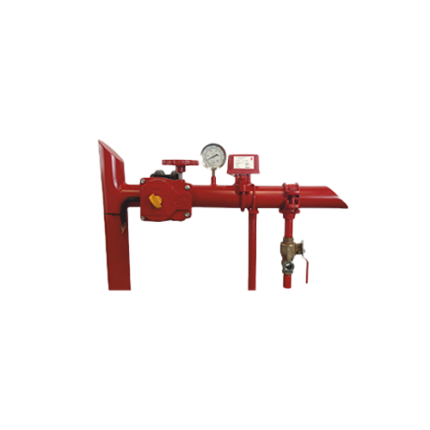
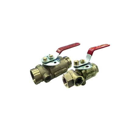
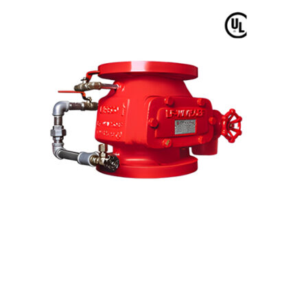
Zone Control Valve Assembly Accessories
Zone control valves are designed to operate utilizing electrical service for actuation. A sprinkler system must be capable of shut down after the fire has been controlled, and for periodic maintenance and modification. Control valves can provide this function. In the simplest system a single shut-off valve may be located at the point where the water supply enters the building.
The Package consists of: Butterfly Valve, Test & Drain Valve, Pressure Gauge, Waterflow Indicator, Supervisory Switch & Water Flow Indicator